Application story
Interactive, modular measuring system for different objects
Application story
Interactive, modular measuring system for different objects
Modular measuring system for rubber seals
The manual measurement of objects can be very labour-intensive and time consuming. To relieve the employees of a manufacturer of frame seals, phil-vision developed an optical measuring system to check the dimensional accuracy of free form gaskets automatically and precisely.
Previously, a manufacturer of frame seals checked the dimensional accuracy of rubber gaskets at random intervals at a single test station. This measuring and testing process, which was carried out manually by a person, should be automated and run randomly in future.
The development of an interactive system solution presented us with several challenges. The main problem was the almost infinite number of different seals that had to be measured. In addition, the solution had to be highly accurate, easy to operate and be able to be adapted quickly and flexibly to a wide variety of seals. Last but not least, the customer wanted a cost-efficient system that they could install themselves.
This task was successfully solved with a precise optical system based on a high-resolution camera with telecentric lens and different lighting scenarios.
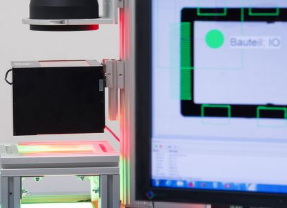
Choose the right illumination
To capture the edges of the objects as precisely as possible, a telecentric lens was used in addition to a high-resolution industrial camera. This eliminates curvature-related distortions and perspective shifts. To represent the outer contours of the seals as accurately as possible, collimated front light is used, so that only the outlines of the respective object are visible in the captured image.
For further inspections on the surface of the seals, a coaxial backlight illumination is used, which focuses on the upper part of the rubber and clearly displays it. Depending on the inspection task, the software switches between the two illumination scenarios via an illumination controller.
Exact calibration - exact measurement
To set up the system, a calibration must be performed first. This happens in Teledyne DALSA's Sherlock image processing software using a calibration plate that is placed above the front light at the sme height as the seals that need to be measured and illuminated subsequently. This process is necessary to eliminate any manufacturing tolerances and inaccuracies in the optical components and enables output of the results in metric values, as the conversion factor can be precisely determined with the aid of the calibration plate and be stored accordingly.
Once the calibration is completed, the customer's PLC starts the test procedure via TCP/IP. When the operator has selected the object to be measured via a user interface created individually for this customer, this input is transmitted to the image processing software. The software then loads the target values (CAD data) of the frame seal to be inspected.
In the first step, the camera captures the test object on a glass plate illuminated by the backlight. The user can see the images live on the screen and if necessary, he can correct the position of the seal to be inspected immediately.
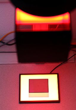
Measuring thickness, distance, and angle
Once everything is set correctly, the measuring process begins. The rubber thickness is measured along the seal edges and at the same time the shape of the rubber seal is examined for distances and angles. The results are compared with the set values and the calculated deviation in micrometres is displayed on the user interface. Once this step has been successfully completed, the operator switches on the front light via the GUI and the illumination controller.
In a second step, the surface of the seal is now compared with the sample data again and checked for defects such as cracks or holes. Discrepancies are displayed on the screen. If the operator is satisfied with this step, he acknowledges it, and all previously measured values are sent to the PLC. The image processing software then waits for the operator to enter the next test object, to start the next measuring process.
Accurate to the milimetre
This system achieves measuring accuracies of approximately 50 µm with an image size of 200 x 150 mm. With thin objects and somewhat smaller image fields, accuracies smaller than 10 µm can be achieved.
The optical inspection system saves the customer time-consuming and always subjective - measuring and manual testing and ensures micrometre-precise measurement and automated process control. Thanks to the modular design, adaptions to different seal and rubber types can be implemented easily. The use of flexible image processing tools also makes it easy to integrate further functions and to expand the system in case of future additional requirements.
More application reports
Would you like to know more?
Do you have questions about our application reports or other news from our blog?
Just get in touch with Astrid Sommerkamp by phone +49 89 125094354 or email

 English (EN)
  Deutsch (DE)
