
Is telecentricity really the only solution for precise optical measurement?
To answer this question and to better understand the different options our calculators offer, we will go into some basic explanations around optical metrology.
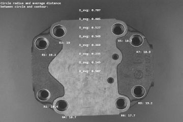
When we talk about high-precision measurement, it is usually about measuring how wide and/or how high an object is. In addition, features of the object such as drill holes, holes, individual components, adhesive beads, or the like should be meaured in width or height.
Or as an example, it is necessary to know where these objects are located in relation to the edges of the entire object, including information about the distance to the edge or the rotational position.
Human eye vs camera technology
Humans usually recognise the edges of an object or feature immediately with their eyes. For image processing, this is not always so clear, as the technology is ubject to many physical limits and conditions.
When a machine vision system examines the borders of an object, we speak about "edges". These edges are transisitons from light to dark, or vice versa. The transisiton direction can also change "across the edge". These transitions are extracted with so-called edge tools. It is important to note that the image is projected via the optics onto a sensor that has a finite number of pixels (individual light-sensitive elements of a sensor). Usually, the accuracy describing where exactly the transition from light to dark has taken place is limited to the number of pixels on which the edge is imaged. In addition, using a sensor you cannot map the transisiton from black to white from one pixel to the neighbouring pixel. Some light always falls from the dark side onto the pixel that actually measures the bright area and vice versa. To represent an edge, you need at least 2, better 3 pixels over whcih you can measure an edge.
Problem sampling theorem
Just for the sake of completeness, this classical problem of physics should be mentioned as Nyquist's sampling theorem, which states that you must sample every signal with twice the frequency of the resolution. This fact represents the limit of optical resolution.
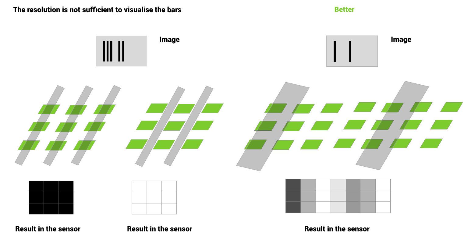
When our calculator asks for the width of the measuring field, we want to know how large the image area to be measured is and which part of the image is mapped onto the wide side of the sensor. This way we know for example how many pixels we have available per mm.
The next question that needs to be answered is the resolution. What is the smallest defect or object you want to see and how big/how wide is it? Based on this information and the number of pixels per mm, we can calculate the required resolution or, conversely, define the necessary number of pixels of a camera and the other required optical components from your specifications.
Pixel-accurate measurement vs subpixel-accurate measurement
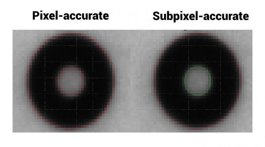
If the edges of a measured object are sharp and it is known from the structure of the system how the data is generated, these edges can also be measured in such a way that valid results "within" a pixel are obtained. In this case it is possible to go beyond the actual resolution pixel/mm up to a factor of 10 and measure "between the pixels". This mathematical increase of resolution is called "subpixeling". Caution is advised with this technique, as no real data is used but interploated and the question needs to be asked whether results in the subpixel range make sense and represent real measured values.
Since we can only use subpixel techniques when the edges have a certain texture and the system fulfils certain conditions, we have defined several "tasks" or "acquisition situations" in our calculators.
Backlight measurements
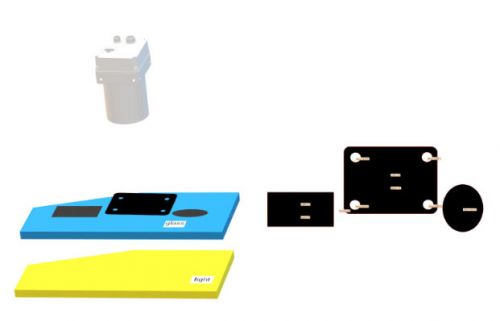
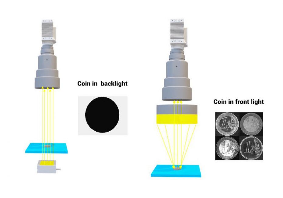
The simplest case in optical metrology is the use of a backlight illumination. Here, the object to be measured is positioned between an illumination and the camera, ideally with some distance to the illumination. This camera thus Looks "into the light" and the object is seen only as a shadow, just as the moon (object) becomes black when it moves between the observer (camera) and the sun (light source) during a lunar eclipse.
In this case, the light rays hit the object from "infinity", i.e., very parallel, or graze the object and hit the sensor. Wherever the object is "hit", the pixels in the image become black/dark, everything else remains white/bright. The transistion, i.e., the edge, can now be measured very well, even with subpixel accuracy.
However, it must be clear that only the "outermost contour" can be measured. All elements on the object remain black for the camera, i.e., if elements on an object are to be measured, the backlight variant is unsuitable.
For highly accurate measurements, a parallel light direction is very important. In real measurement technology, this must first be established with the right illumination and supported by the optics, e.g., telecentric lenses. Therefore, we distinguish between telecentric and endocentric measurement techniques in our calculators.
You can find more detailed information on these measurement techniques in our whitepaper
"Measurement accuracy is the key: telecentric vs endocentric measurements"
Example coinage
Let"s take the example of coinage. Here the user assumes that a coin has a minted edge that is 90° to the surface and is assumed to be very sharp. But this is not true, because the coin has a very slight belly, and this is measured.
Worse still, the minting may displace some metal which may protrude, perhaps "right at the bottom" of the coin. In this case, the outermost tip of the displaced metal would be measured and not the actual edge seen "from above". Therefore, it is very important for the understanding of the results to know where exactly a measurement is taken. In the case described, it might be that this protruding chip is a flaw that is to be detected and measured.
However, the conditions and limitations explained so far are only the "simple" physical conditions. For a high-precision measurement technique, i.e. measurements in the range of 1-2 µm and below, further physical properties such as
- vibrations (which can be countered with short exposure times or heavy mechanics)
- diffraction at the gap (i.e. the property of the object edges or the optical settings)
- the wavelength of the light (if only one colour is used, or possibly infrared where the wavelength itself is already 1 µm long)
must be taken into account. However, detailed explanations of this are beyond the scope of this article, which is already very broad.
Front light measurements
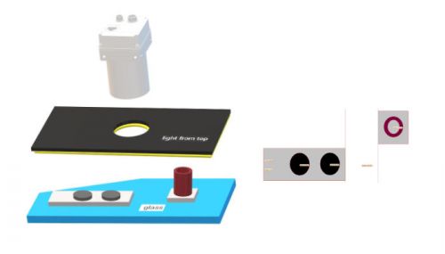
If we want to measure elements "on" an object, we must work with front light. In this illumination situation, further problems often arise regarding light direction and edge properties. To be able to explain these better, we need to go into some more physical properties of light.
When light hits an object, it is normally absorbed a bit by the object, i.e., some of the light remains as energy "in the material", but mainly is reflected, a fact that is used in image processing. The reflection takes place according to the simple law of angle of entry = angle of exit. So far so simple - more difficult to comprehend but important for understanding optical metrology or image processing in general, is: The camera (incidentally also the eyes) does not see the objects. It only sees the light reflected from the object. Therefore, we need to control how the light is directed onto the object so that its reflection ends up in the camera, or in the lens. In addition, we must consider how the object is constructed, i.e., where the light rays hit and at what angle they are reflected. This is where the target comes into play. If the edge is angled 90° and sharp, the edge position can be measured exactly. However, if the edge is slightly rounded, as is the case with most real objects, the light is reflected over all angles and only a part lands on the sensor. However, this is usually neither the beginning nor the end of the curvature, but somewhere in between.
If an object to be measured is manufactured identically, actually a basic requirement for series production, and this object only has a slight curvature, the edge can be measured relatively accurately in a repeatable light and position situation at the same point.
This is the situation when we speak of "clear edges" in our calculator. For us, clear edges are high-contrast edges, but they can also be easily recognisable transitions from one material/surface to another, or from one colour to another. In both cases, the necessary contrast is usually created by different absorption properties.
In contrast, we speak of "unclear edges" when object edges have little contrast, or large or changing curves, or are made of different materials/surfaces with similar strong absorption properties and therefore too little light is reflected onto the sensor.
In principle, we can also measure "unclear edges", but this requires some tricks and more effort and usually does not provide the accuracy as "clear edges".
Validation of optical measurement systems
As the last fundamental point of (optical) measurement technology, we would like to deal with the validation of the measurement system or the comparability with other measurement methods.
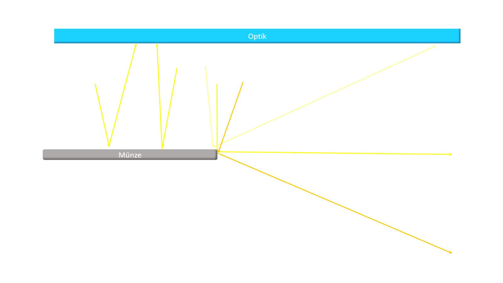
Let's go back to the situation of the "clear edge" with a small rounding and teh example of coin measurement. We assume that the coin is bent 90° at the transition from the surface to the edge and the radius of the bend is small. In this case, it is difficult to compare the measurement results of the optical measurement system with those of a mechanical calliper that simply measures the outermost metal displacement of one side and the outermost metal displacement of the other side.
In reflected light, we measure the point with the highest reflection on the round bend with the corresponding point on the opposite side of the coin. These two measurement (mechanical/optical in reflected light) cannot match because they were taken at different positions. For an exact match, the round bend should have been measured in a laboratory with a tactile measuring system to find out exactly where the point with the highest reflection is in reality and correct some other points, such as the fact that the tactile measuring system measures the rough surface only on the "material mountains" and the image processing also reaches the "valleys" and averages them.
This is as complicated as it sounds. For this purpose, there are procedures such as MSA (Measurement System Analysis), which confirm resilient metrology accepted by auditors.
If you would like to know more about this topice, we refer to our whitepaper
"Measuring system analysis of optical measuring systems"
What can we do for you?
We would be happy to discuss your ideas and requirements in detail and develop a specialised solution together with you, tailored to your individual needs.
Call us at +49 89 125094350 or complete the contact form.
 English (EN)
  Deutsch (DE)